INSTALLATION OF SENSORS AND DATA ANALYSIS OF A VERTICAL AXIS WIND TURBINE FOR DOMESTIC USE
Author: Serda Mena, Antonio
Supervisor: Romeo Granados, Juan
Colaborating institution: ICAI – Universidad Pontificia Comillas
Introduction
Given the rise of domestic self-consumption of electrical energy in Europe in recent years and the changes in the laws in Spain in relation to this matter, new technology arises to supply this demand. Currently, this demand is covered mostly by photovoltaic panels, since there is still much room for improvement in the field of wind energy for domestic use.
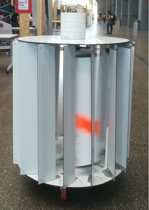
Due to the lack of a generalization of this last type of energy as a reference of efficiency and comfort for the domestic consumer, the central idea of this project arises: the “Smart Wind Turbine” or “Smart AG”. This is a prototype of an Arrieus vertical axis wind turbine designed by the supervisor of this project: Juan Romeo Granados. It has five blades that rotate around a mobile axis, which would be connected to an electric motor. At the same time, it is thought that in the future the wind turbine will have an electronic system that allows obtaining maximum efficiency for energy extraction. In order to fulfill this last objective, it is necessary to have the appropriate technologies and tools for it. In this project the necessary systems are developed to:
• Record the switching time values of an anemometer used to measure the linear wind speed.
• Record the switching time values of a Hall or Holzer effect sensor used to measure the angular speed of the turbine.
• Activate an emergency turbine braking system if the specified speed limit is exceeded.
• Calculate the position of the center of mass of the turbine wing profile.
• Calculate the moment of inertia of the turbine.
• Have the wind and turbine speed and acceleration values available for each moment of time, being able to display them graphically.
• Calculate the torque and mechanical power on the turbine shaft, being able to display them graphically.
• Estimate the turbine loss coefficients.
• Draw a prototype of the optimum turbine tracking curve, necessary for the use of vector control devices. To draw the real one, it would be necessary to replace the mechanical power on the shaft with the electrical power generated at each moment by a motor connected to the turbine.
Methodology
Arduino has been used to design the first three functions. These have been installed on an Arduino Uno board to which an anemometer, a Hall sensor, a sevomotor and a bluetooth module have been connected. The anemometer used has three cups and switches twice per lap. The Hall effect sensor is attached to the turbine casing and detects a switch every time a blade passes near it. Each blade has a magnet attached to its central point. The servomotor is installed in a brake system designed by the project supervisor. When the wind or turbine speed exceeds a previously specified limit, the servomotor is activated. The bluetooth module is used to send the switching time data of the anemometer and the Hall sensor to a computer for further analysis. Everything related to sending data through this system has been designed by the student Javier Colinas Cano in his respective Final Degree Project: “Measurement, transmission and data analysis ofa vertical axis wind turbine for domestic use”.
Matlab has been used to design the rest of the functions. The calculation of the position of the center of masses of the wing profile, as well as the calculation of the moment of inertia of the turbine, has been carried out by discretizing the wing profile area and operating according to the position of each point of the system. When it comes to the moment of inertia, it is crucial to add the moments of the other turbine elements, in addition to the ones of the blades. Obtaining speeds for each instant of time is achieved thanks to the switching time values sent to the computer by the student Javier Colinas Cano. With these vectors, the speed values for these switching times are calculated using time differentials. Finally, the speed values are interpolated for each instant, having, in this case, a resolution of [ms]. Acceleration can be calculated using speed values. Acceleration, in addition to the moment of inertia of the turbine, allows obtaining the torque and the mechanical power for each moment of time.
Results
The programs presented in this project together with the devices indicated therein achieve the proposed objectives. However, there were sudden failures in data collectioninitially, causing some of the Hall sensor commutations not to be detected at high turbine speeds. This was solved by creating different modes of use in the Matlab program that spot the error and correct it by an approximation. In addition, the method used to measure the speed of the turbine, using a magnet on each blade, produced errors of measurement of the acceleration, since the magnets were not perfectly positioned, with the same angle between all of them. To solve this, two additional modes of use were added to the program: one of them measured the time variations of each of the five magnets in relation to itself and the other suppressed all the magnets except one, since this prevented errors in the detection of the switching to a greater extent.
Regarding the loss coefficients estimation program, it performs the calculations based on a turbine braking curve where no external torque is applied to it. Depending onhow many points of the curve it is decided to take, an equivalent number of coefficients is calculated, their order being ascending. Theoretically, the higher the order of the coefficient, the lower its value in this type of movement, being all of them positive and reaching a point from which they are negligible. However, the turbine presents vibrations during its movement, so when applying the program, coefficients that model these oscillations are calculated, being them inseparable from those that would exclusively model the losses.
Finally, the program for obtaining the prototype of the optimum turbine tracking curve functions properly. Even so, it would be necessary to install a wattmeter at the output of an electric motor connected to the turbine axis in order to obtain the real curve to be programmed in the pertinent vector control devices.
Conclusions
This project presents a series of useful tools, procedures and recommendations aimed at facing the first steps of the development of a wind turbine of these characteristics. Throughout it, errors that may have occurred are detailed, as well as their solutions.
After this project, comes the improvement of the turbine design based on the results obtained thanks to the execution of the programs shown here. For obtaining electrical energy and its subsequent transmission to the grid, devices such as an electric motor, power converters or a gearbox, if necessary, must also be chosen and installed
Links
For a complete explanation about how the project works go to Repositorio Comillas.
For the necesary codes to make it function go to my repository on Github.
Cite as:
A. Serda Mena. (2020). Instalación de sensores y análisis de datos de un aerogenerador de eje vertical para uso doméstico. http://hdl.handle.net/11531/41777